


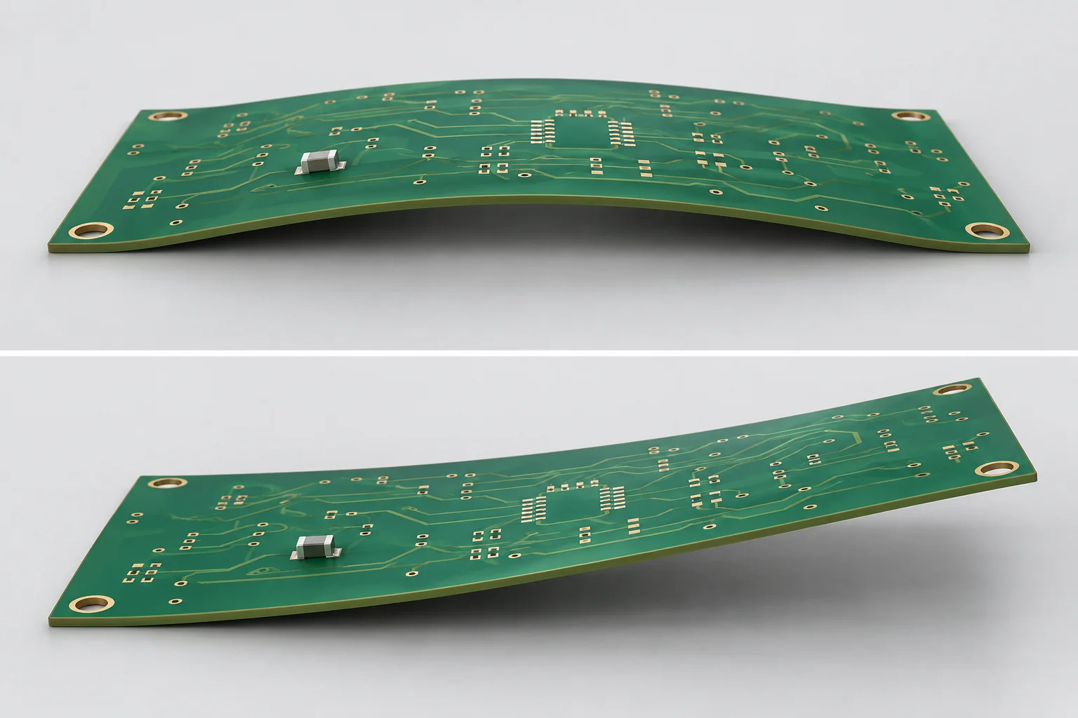
For surface mount PCB jumpers, record whole-board bow, twist and local under-bridge clearance separately. A board-level percentage cannot directly determine one local gap. IPC-TM-650 2.4.22C covers specified boards and panels and explicitly excludes the special considerations needed for assemblies. A bare-board report alone cannot characterize every soldered assembly condition.
Bow and twist describe different shapes
IPC's public revision C and Eurocircuits' explanation describe bow as approximately cylindrical or spherical curvature, with rectangular-board corners remaining coplanar. Twist involves diagonal deformation with one corner outside the plane of the other three. Neither definition gives every local height between jumper feet.
Board length, width or diagonal enters the applicable percentage evaluation. Local clearance is a distance at a specific assembly location, typically in mm. Identical board percentages can coexist with different local curvature. Do not distribute gap change by the ratio of jumper span to total board length.
| Record | Required conditions | Does not replace |
|---|---|---|
| Bare-board or panel bow | Method, direction, dimensions and constraint | Local soldered clearance |
| Board twist | Corners, diagonal and procedure | Simple maximum-height/length calculation |
| Assembly shape | Components, weight, support and fixing | Free bare-board results |
| Local under-bridge distance | Reference, points, temperature and minimum mm | Board percentage or electrical insulation approval |
Corner constraint is part of the method
Revision C contains production and referee procedures with defined support, constraint and calculations. The public document is dated June 1999; confirm the contract's method edition and requirements. This page does not establish one acceptance percentage for every PCB.
Assemblies include component weight, connectors and structural fixtures. State whether the board is free, fixture-supported or installed in an enclosure. If a fixture flattens the board, record that constrained state rather than reporting it as free shape.
Keep thermal and process states separate
Incoming bare boards, cooled post-reflow boards and boards at working temperature represent different conditions. The IPC method normally uses standard laboratory conditions unless otherwise specified. Room-temperature results do not establish shape during reflow. A hot measurement requires an appropriate object definition, support, thermal process and method.
For an investigation, retain board identity, approved inspection stages, images, point maps and support records with process history. Do not flatten a board through unapproved force, repeated bending or heating and then treat it as the original condition.
Connect local inspection to the jumper drawing
For surface mount PCB jumpers, provide the board layout, bridge and foot locations and nearby obstacles. Inspect relevant local areas under the same installation and temperature conditions when board shape affects clearance.
Post-reflow jumper clearance explains the local gap definition. Keep both records, avoiding duplicate allowances for a deformation already included while retaining effects that remain outside the model.
Common questions
Does acceptable global bow guarantee bridge clearance? Check the actual local assembly and its requirements.
Can the board be fixed during measurement? Follow the approved method and identify the fixing state; do not mix it with free-state data.
References
IPC-TM-650 2.4.22C; Eurocircuits bow and twist explanation.
The cover is an AI board-shape illustration with exaggerated distortion, not a Hongchuan product or inspection result. No universal bow, gap or insulation limit is specified.