


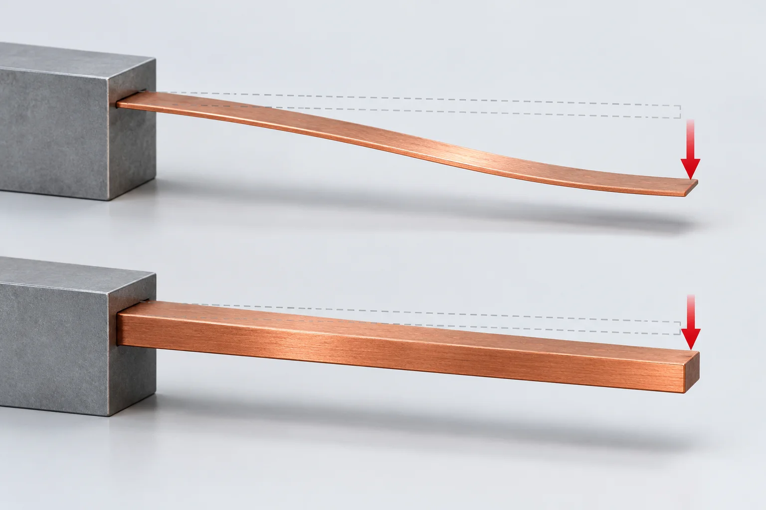
PCB copper busbar bending displacement depends on elastic modulus, section orientation, free span and support. For a uniform straight beam with rigid clamping, a transverse tip load and small-deflection linear elastic behavior, tip displacement is δ=FL³/(3EIb). A rectangular section has Ib=bt³/12. With other inputs unchanged, doubling t divides displacement by eight; doubling L multiplies it by eight.
Draw the load direction and effective support
MIT's elastic-beam course and cantilever-testing lecture treat modulus E, second moment Ib and boundary conditions separately. Ib is geometric and uses mm⁴; it is not electrical current. Here t is section height in the bending direction and b is its width. Reorienting the section requires redefining these directions.
L runs from the effective fixed end to the load point. Overall length, hole spacing and unsupported length may differ. Solder, bolts and PCB compliance can depart from ideal rigid clamping. Do not automatically treat soldered board hardware as a laboratory cantilever fixture.
Keep one consistent unit system
For a hypothetical calculation, assume E=100000 N/mm², F=1 N and b=10 mm. This E is not Hongchuan material data. The qualified model gives:
| Thickness t | Free span L | Ib | Tip displacement δ |
|---|---|---|---|
| 1 mm | 20 mm | About 0.8333 mm⁴ | 0.032 mm |
| 2 mm | 20 mm | About 6.6667 mm⁴ | 0.004 mm |
| 1 mm | 40 mm | About 0.8333 mm⁴ | 0.256 mm |
The values compare geometry within one model; they do not establish product load capacity. Recalculate when multiple inputs change. Model stiffness k=F/δ has units N/mm when force is in N and displacement in mm.
Check stiffness and strength separately
Stiffness describes load versus displacement. Strength assessment also needs stress, material condition and applicable failure criteria. A stronger temper does not establish a proportional increase in elastic modulus. Do not substitute tensile strength Rm for E.
Holes, bends, thinning, contact slip or large rotations may make a straight-beam model inadequate. Include PCB support, joints and external conductor loads, using appropriate analysis and assembly validation. This example does not calculate fatigue life, resonance or short-circuit withstand.
Specify the displacement that matters
For custom PCB copper busbars, identify load direction and location, fixing points, board support and allowable displacement with drawing and material revisions. A measurable requirement allows thickness and support options to be assessed.
Busbar tensile-report properties provide material evidence. Geometry and boundary conditions remain separate inputs to a displacement estimate.
Common questions
Will twice the thickness always produce one-eighth the displacement? Only under the stated model with other inputs unchanged. Validate the real connection.
Does a higher-strength copper remove the need for support? Obtain relevant modulus and strength data and assess the complete load path.
References
MIT elastic beams and tip-loaded deflection; MIT cantilever stiffness, section geometry and compliant supports.
The cover is an AI beam concept with exaggerated deformation, not a Hongchuan test or measured equal-load comparison. Examples establish no material modulus, allowable load or displacement rating.