


Choose the load behavior for a PCB solder terminal test before comparing results. Constant current (CC) regulates current, constant resistance (CR) establishes a resistance relationship, and constant power (CP) regulates load input power. In applicable steady DC operation, CR uses I=V/R and CP uses I=P/V. Equal starting current does not imply equal current after voltage changes.
Identify the controlled quantity
Keysight's public electronic-load overview and GW Instek's mode explanation distinguish CC, CR, CV and CP. These are target relationships within the instrument and source operating ranges and protection limits.
This page compares steady DC CC, CR and CP only. V is voltage at the electronic-load input and P is power absorbed there. That power is not automatically terminal heating. Identify cables, PCB paths and other components between the source and load, including voltage sensing locations.
Compare a common 24 V, 10 A starting point
Assume CC=10 A, CR=2.4 Ω and CP=240 W, with source and load remaining in control throughout the comparison. All draw 10 A at 24 V. At a 20 V load input:
| Mode | Setting | Current at 24 V | Current at 20 V |
|---|---|---|---|
| CC | 10 A | 10 A | 10 A |
| CR | 2.4 Ω | 10 A | About 8.33 A |
| CP | 240 W | 10 A | 12 A |
CP current varies inversely with voltage, not linearly across an arbitrary range. These are separate hypothetical steady operating points. They do not establish stable operation of a real source at 20 V or any terminal or equipment rating.
Use actual current for heating comparisons
If terminal resistance is additionally assumed unchanged, increasing current from 10 A to 12 A changes I²R heating to 1.44 times the original value. It does not establish a 1.44 temperature-rise ratio. Real resistance, connection state and cooling need assessment.
A specified-current comparison may use suitable current control under an approved plan. A constant-power-device simulation needs its corresponding mode and actual operating evidence. Do not change modes between samples and compare terminal performance using only the same “240 W” label.
Retain operating limits and protection state
Record source and load models, mode, settings, measured voltage/current and current-limit, undervoltage or overpower states. Once protection or a control boundary is reached, actual behavior may leave the ideal relationship. A setting is not evidence that it was maintained.
Startup and dynamic response need separate measurements. The static table predicts neither oscillation nor peak or protection transitions. Qualified personnel should use equipment instructions and approved procedures, with suitable cables and fixtures.
Make terminal results comparable
For PCB solder terminals, connect load mode to actual-current records and retain drawings, assembly, measurement points and environment. Identify changes in external conductor geometry, support or contact condition.
Capacitive-load startup current addresses switching on and off. A steady-state reading does not cover the complete current history.
Common questions
Does a 240 W load display mean the terminal dissipates 240 W? It generally describes load input; assess terminal loss from its actual drop or resistance.
Does CC guarantee the set current? Confirm operating range, protection and measured records.
References
Keysight electronic load fundamentals public overview; GW Instek electronic load modes.
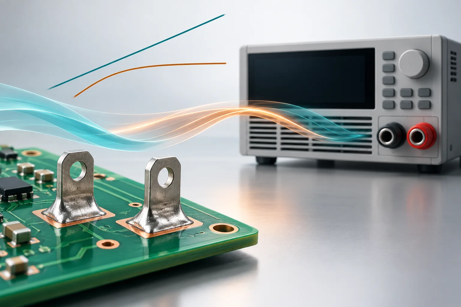
The cover is an AI load-test concept with no actual wiring or measured data. All examples are hypothetical and establish no terminal current, temperature-rise or instrument capability rating.