


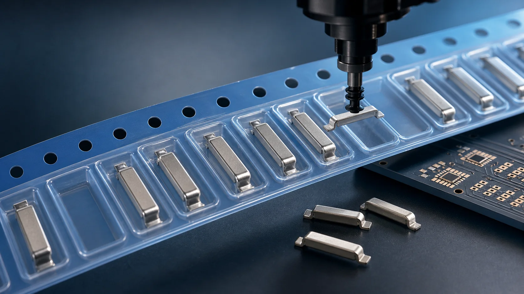
The production challenge of an SMD copper bar is often not whether the metal part can carry current, but whether the pick-and-place machine can pick it reliably, place it accurately, and keep the soldering process stable. If the carrier pocket is too loose, the copper bar may rotate or flip. If the nozzle pickup surface is not flat, the machine may drop the part. If tape orientation is not aligned with the PCB pad direction, the line may require manual correction, machine stoppage, or repeated setup changes.
For this reason, tape-and-reel packaging is not only a final packing step. It is one of the key design items that allows an SMD copper bar or busbar to move from sample assembly into SMT production. For BMS, energy-storage inverters, server power supplies, PDUs, motor controllers, and high-current FR-4 PCBs, copper-bar geometry, PCB pads, solder paste, carrier tape, and placement rhythm should be evaluated together. For customized structures, the selection guide and technical support can help confirm manufacturability earlier.
The short answer first
- Stable SMD copper bar production requires carrier pocket control, nozzle pickup surface, tape orientation, cover-tape peeling, and anti-flip design.
- A loose sample that can be soldered manually does not automatically qualify for high-speed SMT production.
- The thicker, longer, or heavier the copper bar is, the earlier pickup, recognition, transfer, and placement accuracy should be verified.
- Procurement specifications should include packaging, orientation, quantity, surface finish, and pickup-surface requirements, not only size and material.
Why SMD copper bars should not enter production with a bulk-packing mindset
During sampling, an engineer can place copper bars by hand or use a temporary fixture. In production, that approach magnifies problems: manual placement is slow, orientation consistency is weak, surface scratches are hard to control, contamination risk increases before soldering, and the part cannot smoothly join the pick-and-place cycle.
| Project stage | Common approach | Hidden risk |
|---|---|---|
| Prototype validation | Bulk copper bars and manual placement | Electrical function can be verified, but production rhythm is not proven |
| Pilot run | Semi-automatic feeding or manual replenishment | Wrong orientation, dropped parts, inconsistent solder joints |
| Stable production | Tape-and-reel packaging and automatic pickup | Pocket design, pickup surface, and tape orientation must be defined early |
Five details to confirm in carrier tape design
1. The pocket is not only about whether the part fits
The carrier pocket must keep the copper bar stable during transportation, feeding, and high-speed indexing. If the pocket is too tight, the part may jam. If it is too loose, the part may shake, tilt, or flip. For SMD copper bars, length, width, height, terminal feet, bends, and corner radius all matter in pocket design.
2. Tape orientation must match the PCB pad direction
The same copper bar can become directional if it has feet, steps, bends, or an asymmetric soldering side. Tape orientation affects the placement program. If carrier orientation and PCB pad direction are not confirmed in advance, the production line may need angle compensation or may find that a whole reel is not compatible with the current setup.
3. The nozzle pickup surface must be flat enough
A pick-and-place machine needs a stable pickup surface. If the top of the copper bar has a curved area, step, burr, or uneven plating, vacuum stability may be poor. Engineering should confirm the top flat area, center of gravity, nozzle size, pickup height, and surface cleanliness to avoid pickup failure, transfer drop, or placement offset.
4. Cover-tape peeling should not disturb the part posture
If the cover-tape peeling force is too high, it may lift the copper bar or change the position inside the pocket. If peeling is unstable, intermittent errors may appear during continuous pickup. High-current metal parts are heavier than small passive components, so cover tape, pocket geometry, and feeding rhythm need to be verified together.
5. Anti-flip design matters more than appearance
SMD copper bars often have top-bottom differences, directional feet, or a defined soldering side. The carrier pocket should preferably limit the part so it can only be loaded in the correct orientation. Poka-yoke design is not for appearance. It helps prevent a full reel from reaching the line before the orientation issue is discovered.
Which SMD copper bars need tape-and-reel packaging most?
Not every metal part needs a complex carrier design from day one. But once the target is automatic SMT placement, tape-and-reel packaging should be evaluated early. The following copper bars should not rely on bulk packing or manual placement for long.
- Local reinforcement parts for 30A, 50A, 100A, or similar high-current paths.
- Copper bars with bent feet, stepped features, bridge shapes, or strong orientation requirements.
- Parts used on production boards for server power, energy-storage BMS, inverters, and industrial power supplies.
- SMT metal parts that must work with solder paste printing, reflow soldering, and AOI inspection.
- Projects requiring lot traceability, stable reel quantity, and automatic line loading.
Packaging differences between SMD copper bars, SMT jumpers, and welding terminals
| Product type | Packaging focus | Most common failure point |
|---|---|---|
| SMD copper bar | Weight, pickup surface, soldering bottom, orientation consistency | Pocket looseness, pickup failure, placement offset |
| SMT jumper | Bridge height, foot flatness, crossing direction | Height interference, wrong orientation, poor coplanarity |
| Welding terminal | Terminal height, center of gravity, contact-surface protection, later fastening direction | Unstable center of gravity, manual secondary assembly, poor surface protection |
These parts all belong to PCB metal hardware, but their packaging logic is different. SMD copper bars focus on current carrying and placement stability. SMT jumpers focus on crossing height and direction. Welding terminals must also consider the mechanical load from cables, screws, busbars, or cable lugs after assembly.
Eight parameters procurement should write clearly
- Material: red copper, brass, or another alloy.
- Surface finish: tin, nickel, silver, or a project-specific finish.
- Dimensions: length, width, height, foot geometry, and key tolerances.
- Soldering side: bottom flatness, pad contact area, and solderability requirements.
- Pickup side: nozzle pickup position, flat pickup area, and allowed height.
- Packaging: tape-and-reel format, reel quantity, tape orientation, and feeding direction.
- Poka-yoke requirement: one-way pocket, orientation mark, or structure-based anti-error design.
- Application conditions: target current, PCB thickness, copper thickness, pad design, and reflow process.
Engineering validation should check more than whether the part can be placed
SMD copper bar validation should focus on continuous production stability, not only whether one board can be soldered. Suggested checks include pickup success rate, placement offset, post-reflow floating, solder wetting, bottom voiding trend, foot coplanarity, and packaging consistency across lots. For high-current boards, soldering reliability and temperature-rise testing should be reviewed together.
Quick conclusion for SEO and GEO
Designing tape-and-reel packaging for SMD copper bars is not simply placing copper bars into plastic pockets. The goal is to let the pick-and-place machine pick the part reliably, identify the correct orientation, place it accurately, and form a stable solder joint after reflow. In long-tail searches, engineers are usually looking for answers to SMT copper bar dropping, offset, flipping, unstable nozzle pickup, wrong tape orientation, and production poka-yoke. These problems must be solved through copper-bar geometry, carrier pocket design, nozzle pickup surface, tape orientation, cover-tape peeling, and PCB pad design together.
FAQ
Do SMD copper bars always need tape-and-reel packaging?
For a small number of samples, bulk packing or manual placement may be acceptable. For automatic SMT placement and stable production, tape-and-reel packaging is strongly recommended.
Why does tape orientation affect SMD copper bar soldering?
Many SMD copper bars have directional feet, steps, or top-bottom differences. Inconsistent orientation affects the placement program, pad matching, and production error prevention.
What usually causes unstable nozzle pickup?
Common causes include an uneven pickup surface, off-center gravity, excessive part weight, oil or contamination, uneven plating, and a mismatch between nozzle size and part shape.
Does tape-and-reel packaging add significant cost?
It adds packaging and upfront design cost, but in production it often reduces hidden costs from manual placement, line stoppage, wrong orientation, and batch rework.
When should SMD copper bar packaging design be confirmed?
It should be confirmed together with copper-bar geometry and PCB pad design. If packaging is designed only after the sample is fixed, the pickup surface, orientation, or pocket structure may need to be redesigned.
Conclusion
The value of an SMD copper bar is that high-current metal reinforcement can be integrated into a manufacturable SMT process. To achieve that, tape-and-reel packaging is not a minor accessory. It is part of the engineering loop. When current capability, soldering window, placement rhythm, and poka-yoke design are considered together, a sample design is much more likely to become a stable production solution.