


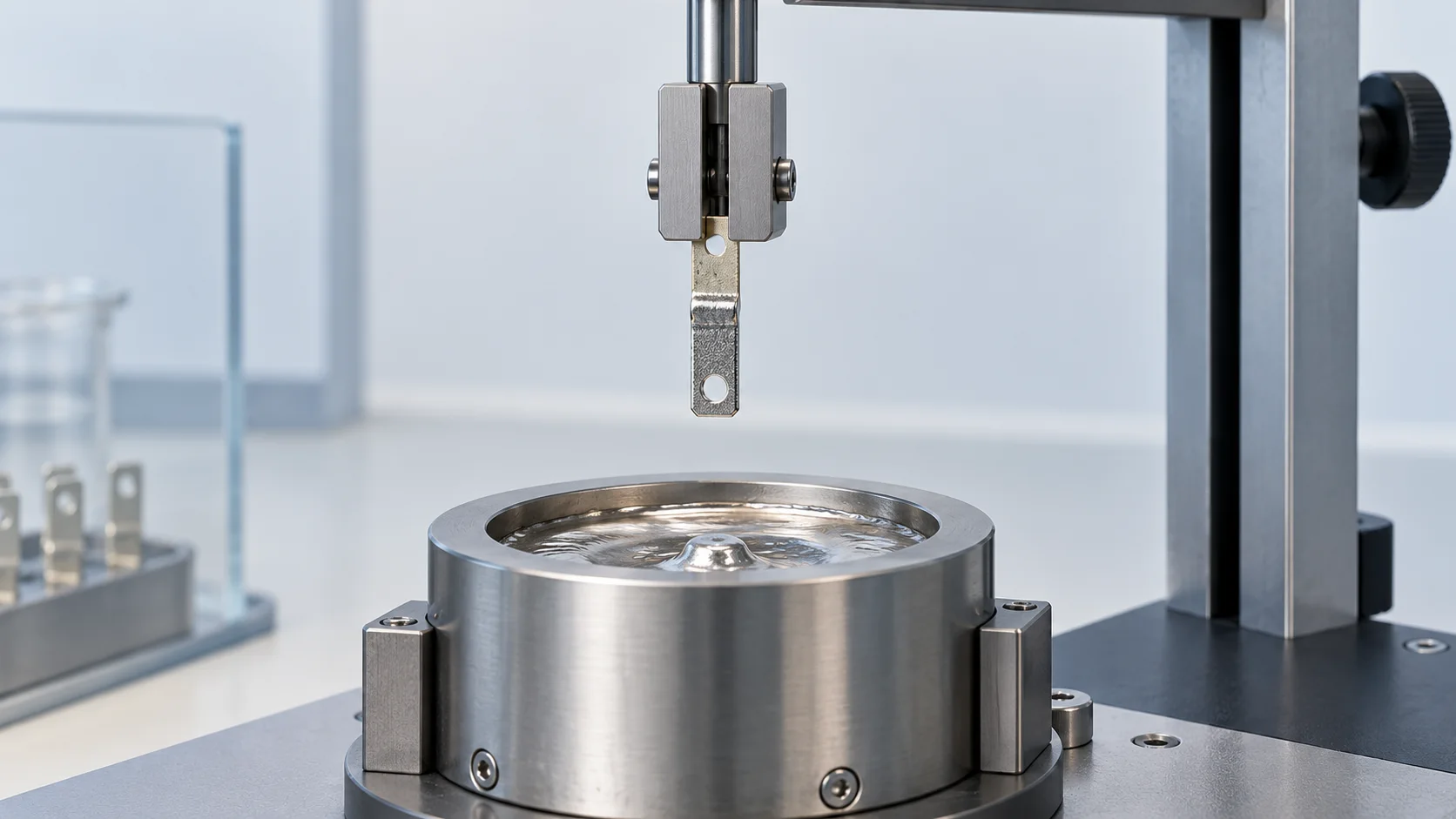
Direct answer Match the solderability test to terminal construction and the assembly process before setting acceptance criteria. Solder coverage, force-versus-time behaviour and resistance to soldering heat answer different questions. A wetting curve alone does not establish lot acceptance or qualify a complete board assembly.
Select a method before sending samples
| Object or purpose | Official method to consult | Clarify in the report |
|---|---|---|
| Leaded devices or leads | IEC 60068-2-20 | Solderability versus resistance-to-heat test |
| Surface-mount terminals | IEC 60068-2-58 | Suitability of dip or reflow evaluation |
| Comparing termination wetting | IEC 60068-2-69 | Solder-bath or globule wetting-balance conditions |
| SMD wetting with solder paste | IEC 60068-2-83 | Paste system and comparative procedure |
The public descriptions of IEC 60068-2-69 and IEC 60068-2-83 caution against using their data as absolute quantitative pass/fail values. If purchasing documents require a wetting-time or force criterion, agree the method, specimen scope and justification with the laboratory and supplier. No universal time or force threshold is proposed here.
Make reports comparable
A practical test request should identify the part and drawing revision, coating stack, production lot and storage history. State the complete standard edition, test clause, preconditioning temperature, humidity and duration. Record solder alloy and flux identity, temperature in °C, time in s, immersion depth in mm, speed in mm/s, specimen orientation and the tested surface.
Request raw curves, photographs, sample count and instrument calibration status. For wetting force, retain the unit and say whether any perimeter normalization was applied. A larger terminal may differ in geometry and thermal mass even if its surface condition resembles a smaller one. Compare lots of the same part under controlled conditions; label every deliberate change.
Bring the evidence back to production
When nominally identical lots differ, first confirm specimen identity and test conditions. Then review coating, contamination, packaging and storage records. After a controlled retest, use the intended PCB, solder and equipment for a pilot assembly evaluation. Keep incoming solderability, process-window results and subsequent connection reliability in separate records so that a corrective action has a clear target.
Common questions
Does passing resistance to soldering heat prove solderability? No. Surviving thermal exposure and forming a satisfactory soldered interface are different test objectives.
Is “test to IEC” enough? Specify the number, edition, method and agreed acceptance criteria. IEC 60068-2-69 also has a 2019 amendment; the contract should identify the edition being applied.
Related products and reading
Explore related products · Reading an XRF coating-thickness report · Send drawings and application conditions
Sources
Sources checked on 6 October 2026. Worked examples explain methods, not HC-SP product ratings or test results. Cover is an AI-generated engineering illustration, not an actual product photograph.