


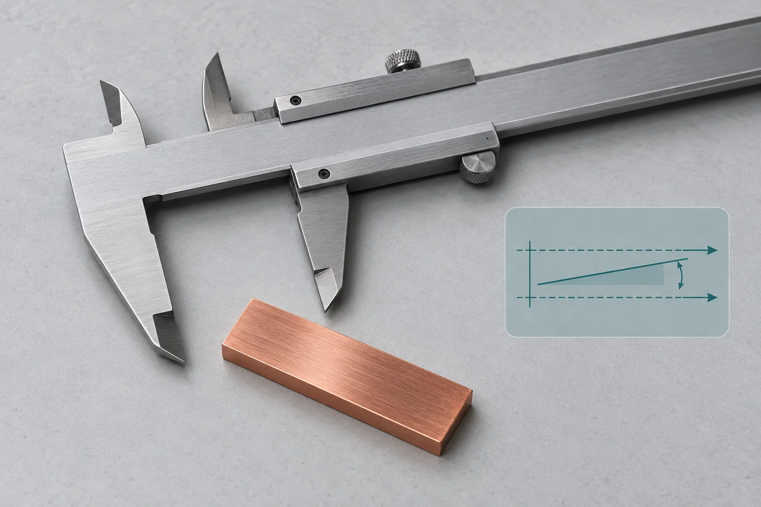
When measuring PCB copper busbar width with a caliper, retain jaw contact position, measuring force and alignment. An offset between scale and measurement axes makes small jaw-angle changes relevant through Abbe error. Display resolution alone does not establish dimensional conformity.
Check the jaws and the contact location
Mitutoyo explains Abbe geometry in its precision-measurement guide. Its small-tool instructions recommend consistent force and measurement close to the jaw roots to reduce beam bending. Follow the actual instrument instructions rather than treating this as a universal setup.
A difference between tip and root readings may include real width variation, burrs and instrument effects. First confirm that both readings address the same section. Do not label the difference as instrument error or select the smaller reading without investigation.
| Item | Action | Retain |
|---|---|---|
| Jaw condition | Clean and check damage, gaps and zero | Instrument ID and checks |
| Contact location | Repeat at the agreed section, near roots where practical | Location and contact height |
| Force and alignment | Use consistent force without squeezing or tilting | Method and repeated readings |
| Workpiece | Separate body width, burrs and deformation | Drawing revision and location |
Use a hypothetical offset calculation
For one idealized small-angle Abbe contribution, e is approximately h times theta. An assumed 40 mm offset and 0.0005 rad angular change give a magnitude of 0.020 mm, or 20 micrometers. Use radians; the sign depends on geometry.
This is not a measured caliper error or a complete uncertainty estimate. Temperature, contact form and part deformation remain outside this simple calculation. Do not apply the assumed value as a fixed correction to production parts.
Define width and thickness methods separately
For PCB copper busbars, agree measurement sections and appropriate support. Thin parts may require review of contact area, force and a suitable thickness instrument or fixture. Additional display digits do not replace that assessment.
Keep original readings, check location effects with a suitable reference and verify the part using an approved alternative method. See calibration, corrections and adjustment for instrument evidence. Apply the agreed decision rule near a dimensional limit.
Questions
Does a correct zero eliminate Abbe error? A closed-jaw check does not validate all contact positions and loading conditions.
Can a tip-to-root difference be a correction? Separate workpiece variation from measurement effects and establish a valid correction first.
Sources
Mitutoyo Abbe principle;Mitutoyo small-tool check points;Mitutoyo caliper measurement guidance
The cover is an AI tool-and-busbar concept, not a contact-measurement demonstration. Geometry is not to scale. No Hongchuan instrument capability or inspection accuracy is claimed.