


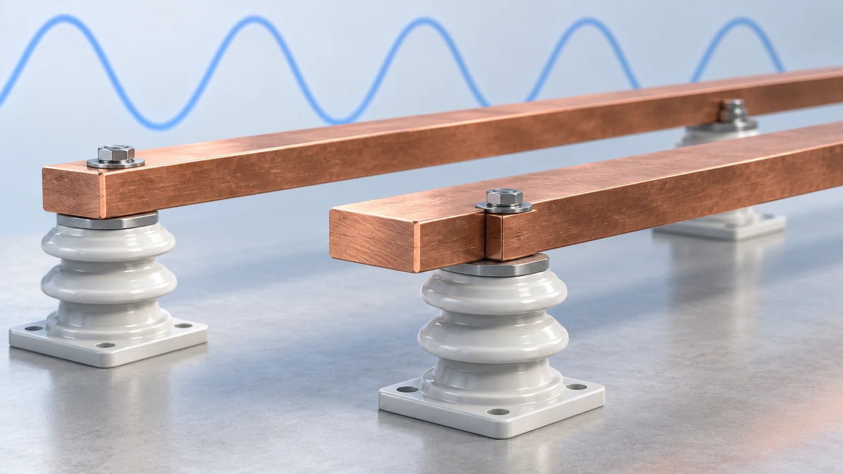
Direct answer Equal copper cross-sectional area does not justify transferring a DC ampacity to AC. Establish the current spectrum in the actual bar, evaluate AC resistance for its geometry and return path, and verify temperature rise in the installed assembly. The switching frequency of a device is not the frequency of all current in its busbar.
Calculate the scale before choosing a model
For nonmagnetic copper, estimate skin depth with δ=√[ρ/(πfμ)]. Use resistivity ρ in Ω·m, frequency f in Hz and permeability μ in H/m; δ is in metres. The following worked values use ρ=1.7×10⁻⁸ Ω·m near 20 °C and μ≈μ₀=4π×10−7 H/m, excluding plating and temperature changes.
| Frequency | Approximate skin depth | Scope |
|---|---|---|
| 50 Hz | 9.28 mm | Power-frequency dimensional screening |
| 400 Hz | 3.28 mm | Reassess AC loss for the same bar |
| 20 kHz | 0.46 mm | Applies to that frequency component |
These calculations are not thickness limits. Skin depth does not mean that the interior carries no current. COMSOL's copper example gives about 9 mm at 50 Hz, a useful order-of-magnitude check with different material inputs.
Include neighbouring conductors
Copper for Busbars treats skin and proximity effects separately. Relative current direction, phase and spacing affect current distribution. Include outgoing and return conductors, parallel branches, joint geometry and nearby magnetic structures. An AC resistance factor for an isolated bar cannot automatically be reused for a different arrangement.
Report S=Rac/Rdc at equal temperature and length. Where the materials and system can be treated as linear, a useful conductor-loss estimate is P≈Idc²Rdc+ΣIh,rms²Rac(fh). Do not assign the highest-frequency resistance to the entire RMS current.
Prepare useful simulation and test inputs
Provide a dimensioned layout, current waveform or harmonic RMS values, material and finish, operating temperature estimate, orientation and cooling boundaries. CDA tables explicitly distinguish emissivity and multi-bar configurations. During assembly tests, record ambient temperature, joint condition and measurement locations. Acceptable conductor loss does not rule out a hot connection.
Questions from design reviews
Are multiple thin bars always better? Recheck proximity loss, current sharing, joints, insulation and assembly constraints. Twice as many bars does not automatically mean twice the ampacity.
Must a DC bar with small ripple be sized entirely for high frequency? Measure ripple magnitude and spectrum, then evaluate its loss contribution before simplifying the model.
Related products and reading
Explore related products · Peak current, RMS and I²t · Send drawings and application conditions
Sources
- Copper for Busbars, sections 2.2.2 and 6.6.5
- COMSOL, Eddy Currents
- Copper Development Association, Busbar Table 4
Sources checked on 6 October 2026. Worked examples explain methods, not HC-SP product ratings or test results. Cover is an AI-generated engineering illustration, not an actual product photograph.