


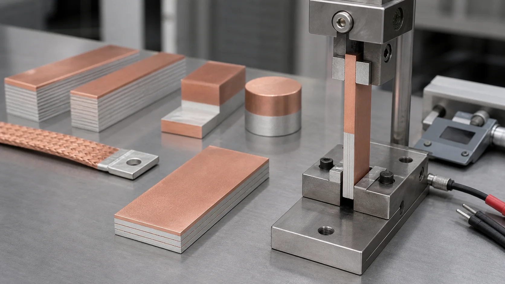
Quick answer: Copper-aluminum composite busbars should not be approved only by copper thickness, aluminum thickness or bulk conductivity. The interface must remain stable under mechanical processing and powered operation. Review peel strength, shear strength, post-bending delamination, contact-resistance drift after thermal cycling, and whether temperature rise concentrates near the Cu-Al interface.
Questions answered on this page
- How should copper-aluminum composite busbar peel strength be tested?
- What do interface delamination, blistering and cracking indicate?
- Why should bending, punching, riveting or bolting be followed by retesting?
- Why can contact resistance increase even when peel strength passes?
- What should battery pack, energy storage and inverter projects verify before production?
Engineering summary
- The key value of a copper-aluminum composite busbar is a stable bonded interface, not simply two metals placed together.
- Peel testing checks resistance to interface separation. Shear testing reflects different assembly loads, so the two tests are not interchangeable.
- Bending, punching, trimming, crimping and bolting concentrate stress near edges and holes. Processed parts must be retested.
- No visible delamination does not guarantee long-term reliability. Retest after thermal cycling, humidity, salt spray and powered operation.
- If heat spreads along the Cu-Al interface or cut edge, check bonding, oxidation, contact pressure and current path together.
Application context
Engineering issues such as “copper aluminum composite busbar peel strength”, “Cu-Al bimetal busbar delamination”, “copper aluminum busbar cracking after bending” and “composite busbar contact resistance drift” usually appear during sample approval, supplier audit, process change or customer failure analysis. The busbar is both an electrical conductor and a structural part. Once the interface becomes unstable, increasing cross-section or tightening torque is usually not a real fix.
Hongchuan Precision Hardware supplies copper-aluminum composite busbars, SMD busbars, PCB welding terminals and SMT nuts for high-current connection systems.
Look at the interface first
Copper-aluminum composite busbars are often used to reduce weight and material cost. In high-current connections, however, failures often appear at the interface, cut edge, bend area, hole edge or bolted contact area rather than in the bulk conductor. Cross-section and theoretical resistance are not enough if bonding quality, processing stress and long-term environment are ignored.
For corrosion and resistance drift, see copper-aluminum connector corrosion, plating and contact-resistance troubleshooting.
What peel, shear and bending tests show
| Test | Main purpose | Result to review |
|---|---|---|
| Peel test | Check resistance to interface separation | Peel force, fracture location, continuous interface opening |
| Shear test | Simulate planar load and assembly stress | Shear strength, sliding, tearing pattern |
| Bending test | Verify interface stability after forming | Outer crack, inner blistering, edge delamination |
| Punching or trimming check | Verify hole and edge processing impact | Burrs, cracks, layer opening, plating damage |
| Post-thermal-cycle retest | Check long-term Cu-Al expansion mismatch risk | Peel strength, contact resistance, temperature rise drift |
Delamination is often an edge problem
It is easy to focus only on the middle of the Cu-Al interface. In production parts, the higher-risk locations are cut edges, hole walls, bend radii and bolted indentation areas. These points combine processing stress, assembly pressure and oxidation. Sample review should separate the flat coupon, edge, hole wall and bend zone instead of relying on one straight strip.
If the part will use bolted assembly, review it with bolted copper-aluminum busbar joint torque, washers and contact resistance.
Mechanical pass still needs electrical validation
Passing peel strength only proves the interface did not separate under one mechanical test. It does not prove long-term low resistance under current. Copper-aluminum composite busbars also need segmented voltage drop, contact resistance and powered temperature-rise testing, especially near cut edges, holes and transition zones.
| Electrical test | Use | Risk signal |
|---|---|---|
| Four-wire contact resistance | Compare initial and post-environment drift | Large sample spread or clear increase after cycling |
| Segmented voltage drop | Locate copper side, aluminum side, interface and joint bottlenecks | Voltage drop concentrates near interface or hole edge |
| Powered temperature rise | Verify real current carrying capability | Hot spots at interface, hole edge or bolt area |
| Post-thermal-cycle retest | Judge long-term pressure and interface stability | Resistance rises gradually and thermal repeatability worsens |
Approve material and processed parts separately
A raw material coupon passing the test does not mean the finished part will pass. Cutting, punching, bending, flattening, drilling, riveting, soldering or bolting can introduce edge cracks or micro-delamination. Keep three sets of data: raw material condition, processed part condition, and post-environment or powered condition. This separates material, process and assembly causes.
Validation workflow before production
- Confirm material structure. Record copper thickness, aluminum thickness, bonding process, interface condition and lot number.
- Run basic peel and shear tests. Build a batch baseline and record fracture location.
- Process real parts. After cutting, punching, bending, crimping or bolting, repeat visual, cross-section and strength checks.
- Run environmental validation. Choose thermal cycling, humidity, salt spray, vibration or repeated assembly based on the application.
- Retest electrical performance. Compare contact resistance, voltage drop and temperature rise before and after processing and environment exposure.
- Define incoming inspection. Put peel strength, delamination criteria, edge quality and resistance drift into supplier acceptance rules.
Common mistakes
- Specifying peel strength but not checking delamination after real part processing.
- Reviewing cross-section only and not measuring interface-area voltage drop or temperature rise.
- Using a bend radius that looks acceptable at first but cracks after thermal cycling.
- Increasing bolt torque as a fix and causing aluminum indentation or higher interface stress.
- Approving hand-prepared samples while production edge and hole quality are different.
RFQ and engineering checklist
- Target current, allowed temperature rise, working environment and life requirement.
- Copper/aluminum thickness, bonding process, peel strength and shear strength requirements.
- Whether the part needs bending, punching, trimming, riveting, bolting or soldering.
- Whether processed parts require cross-section, peel, contact resistance and temperature-rise retesting.
- Incoming inspection plan for appearance, dimensions, interface, edges, holes and electrical performance.
FAQ
Is higher peel strength always better?
Higher peel strength is generally helpful, but the number alone is not enough. Review fracture location, post-processing delamination, retention after thermal cycling, and electrical stability.
Should a bent part be retested if no crack is visible?
Yes. Micro-delamination may not be visible immediately. It can grow after thermal cycling, vibration or powered operation, especially near bend outer edges and cut edges.
Does higher contact resistance mean poor bulk conductivity?
Not necessarily. Interface condition, hole edge, contact pressure, oxide film or assembly surface can reduce the real contact area.
What can Hongchuan support?
Hongchuan can support copper-aluminum composite material samples, dimensional review, interface structure confirmation, processing review and high-current connector selection. Start with the high-current PCB hardware selection guide for early projects.