

SMD copper bars and SMT jumpers are both common metal add-ons for FR-4 PCBs, but they solve different problems. An SMD copper bar is mainly used to share high current, reduce local impedance, and create a thermal conduction path. An SMT jumper is mainly used to bridge a routing conflict so a power path can cross over another trace without adding PCB layers. Selection should not be based only on size or current rating; the current path, solder area, material, plating, placement direction, and tape-reel packaging all matter.
If your project already has wide copper that still runs hot, power traces interrupted by signal routing, interface heating, or unstable manual placement of metal blocks, review SMD busbars and copper bars, welding terminals, and technical support together. The real goal is not one part. It is a high-current path that is low resistance, low temperature rise, solderable, placeable, and repeatable in production.
First separate the two add-ons: copper bars and jumpers are not the same
| Part | Main role | Typical use | Selection focus |
|---|---|---|---|
| SMD copper bar or block | Add metal cross-section and reduce high-current path impedance | BMS, inverter, power module, and charging module power paths | Material, plating, cross-section, solder area, and thermal path |
| SMT jumper | Create a three-dimensional bridge over routing conflicts | Single-sided boards, low-layer-count boards, and dense power routing | Span, height, solder feet, orientation control, and tape packaging |
| Welding terminal | Connect an external cable, busbar, or screw interface to the PCB | Power input/output, service points, and board-to-board current interfaces | Fastening method, contact resistance, pad design, and mechanical strength |
What an SMD copper bar is best at solving
The logic of an SMD copper bar is simple: use a solderable metal body to carry part of the high-current path instead of forcing all current through PCB copper foil. As current increases, impedance and power loss become more sensitive, and heat from local resistance increases rapidly. Widening traces, increasing copper weight, or paralleling layers may no longer balance cost, etching precision, space, and temperature rise.
1. Sharing high current, not decorative copper
An SMD copper bar should be placed on the real power path, not only where the board looks warm. Its value is reducing path impedance, shortening the high-current loop, and moving heat away from narrow copper and local pads.
2. Creating a thermal bridge, not relying on air cooling alone
The copper bar can conduct heat, but the more important job is moving that heat into larger copper areas, a heat spreader, a mechanical base, or another structure that can spread it. Pad design, surrounding copper, via arrays, and the system thermal path should be checked together.
3. Reinforcing high-current contact zones
At power input/output areas, fuse regions, power-device common nodes, and board interconnect points, an SMD copper bar can upgrade fragile local copper into a more robust metal contact area. If screw fastening or external cable service is involved, a welding terminal should also be evaluated.
What an SMT jumper is best at solving
An SMT jumper is more like a metal overpass on the PCB surface. It is not just a wire replacement; it gives a power path a way to cross over another route in a low-layer-count design. When a high-current route is interrupted by signal traces, components, or mechanical restrictions, an SMT jumper can reduce the need for a more expensive layer stack.
- A single-sided or two-layer PCB should not add layers only for one crossing point.
- A power route needs to cross a signal line, sensing line, or local component area.
- The crossing structure should be placed by SMT instead of hand-soldered wire.
- A fixed height and stable solder foot design are needed to reduce manual variation.
Material choice: copper, brass, and plating
Material selection should not be based only on unit price. Copper bars usually prioritize conductivity and heat conduction, while jumpers also need forming strength, span stability, and placement reliability.
| Material or finish | Advantage | Watch point | Best fit |
|---|---|---|---|
| Red copper | Strong electrical and thermal conductivity | Cost and forming stability should match the geometry | High-current copper bars, thermal bridges, and main power paths |
| Brass | Good strength and formability, often more cost friendly | Lower conductivity than red copper, so identical shape does not mean identical current capacity | Medium-current jumpers, support metal parts, and bridge structures |
| Tin plating | Solder-friendly and suitable for common SMT windows | Plating uniformity, edges, and post-solder surface should be checked | Most board-level copper bars, jumpers, and terminals |
| Nickel or combined plating | Better wear and environmental resistance | Soldering window and contact requirements should be confirmed early | Frequent-service or higher-contact-stability applications |
Pad and structure design points
Board-level metal add-ons are reliable only when the PCB land pattern and assembly details are also correct. Many failures are not caused by a copper bar being too small, but by pads that cannot receive the current and heat properly.
- Let current enter the PCB smoothly through large solder areas instead of sudden neck-down sections.
- Match pad area to the thermal mass of the copper part to avoid poor wetting or weak solder joints.
- Design via arrays together with the copper-bar pad when high current crosses layers.
- For SMT jumpers, confirm span, height, and safe clearance over the traces below.
- If pick-and-place is required, the top surface, rounded edges, and center of gravity must support nozzle pickup.
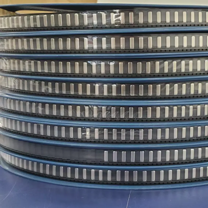
Why tape-reel packaging matters
If a high-current metal part is supplied only in bulk and placed by hand, prototypes may work, but production consistency will be difficult. Industrial SMD copper bars and SMT jumpers should use carrier tape and reels whenever possible so pick-and-place equipment can handle them like other SMD components.
- The pocket should control flipping, skewing, and feeding jams.
- The top surface should support stable nozzle pickup, not only soldering performance.
- Orientation-sensitive jumpers need clear anti-error design.
- Packaging affects placement speed, reject rate, and manual-intervention cost.
Fast selection conclusion
If the board-level high-current path is hot, copper is too wide, or local impedance is high, start with an SMD copper bar or SMD busbar. If the problem is routing conflict, limited layer count, or crossing a signal trace, start with an SMT jumper. If the problem is external power input/output, screw fastening, or service access, start with a welding terminal. These parts can be combined, but they should not be treated as interchangeable.
FAQ
Are SMD copper bars and SMD busbars the same?
In many engineering discussions the terms overlap because both refer to board-level metal parts that share current and reduce impedance. More strictly, busbar usually emphasizes system-level current collection and distribution, while copper bar describes the physical form and local reinforcement.
Can an SMT jumper replace a high-current copper bar?
Not automatically. A jumper is mainly for crossing routing conflicts. Its current capacity depends on material, cross-section, solder feet, and temperature rise. If the goal is main power-path reinforcement, an SMD copper bar or busbar is usually the better starting point.
Is a thicker SMD copper bar always better?
No. More thickness can increase cross-section, but it also increases thermal mass, soldering difficulty, placement requirements, and cost. Current target, temperature rise, pad area, and assembly capability should be judged together.
Why not just use heavy-copper PCB instead?
Heavy-copper PCBs can solve part of the current problem, but they may add cost, lead time, etching limitations, and fine-line compatibility issues. Local SMD copper bars or jumpers often reinforce only the critical current path while preserving a more standard PCB process.
Conclusion
High-current FR-4 PCB design is a balance among impedance, temperature rise, layout space, and production efficiency. SMD copper bars answer the question of how current can flow with lower resistance. SMT jumpers answer the question of how a blocked route can cross over. Tape-reel packaging answers the question of how the solution can be built repeatably. These three decisions together are what make board-level metal add-ons valuable.