

In an EV charging power module, a welding terminal usually deserves earlier consideration than directly soldered wires when the connection point is fixed on the board and the project wants a cleaner, better-defined conductive interface. At the same time, it is not the default answer for every position. The first question is whether that section acts as a board-level interface, a main-current transition, or a longer flexible route.
For projects that involve AC/DC power modules, cabinet-level distribution, and downstream assembly, it helps to review the welding terminal page, applications page, and SMD busbar page together. That makes it easier to assign the right role to terminals, busbars, and harnesses instead of forcing one connection style to cover the full path.
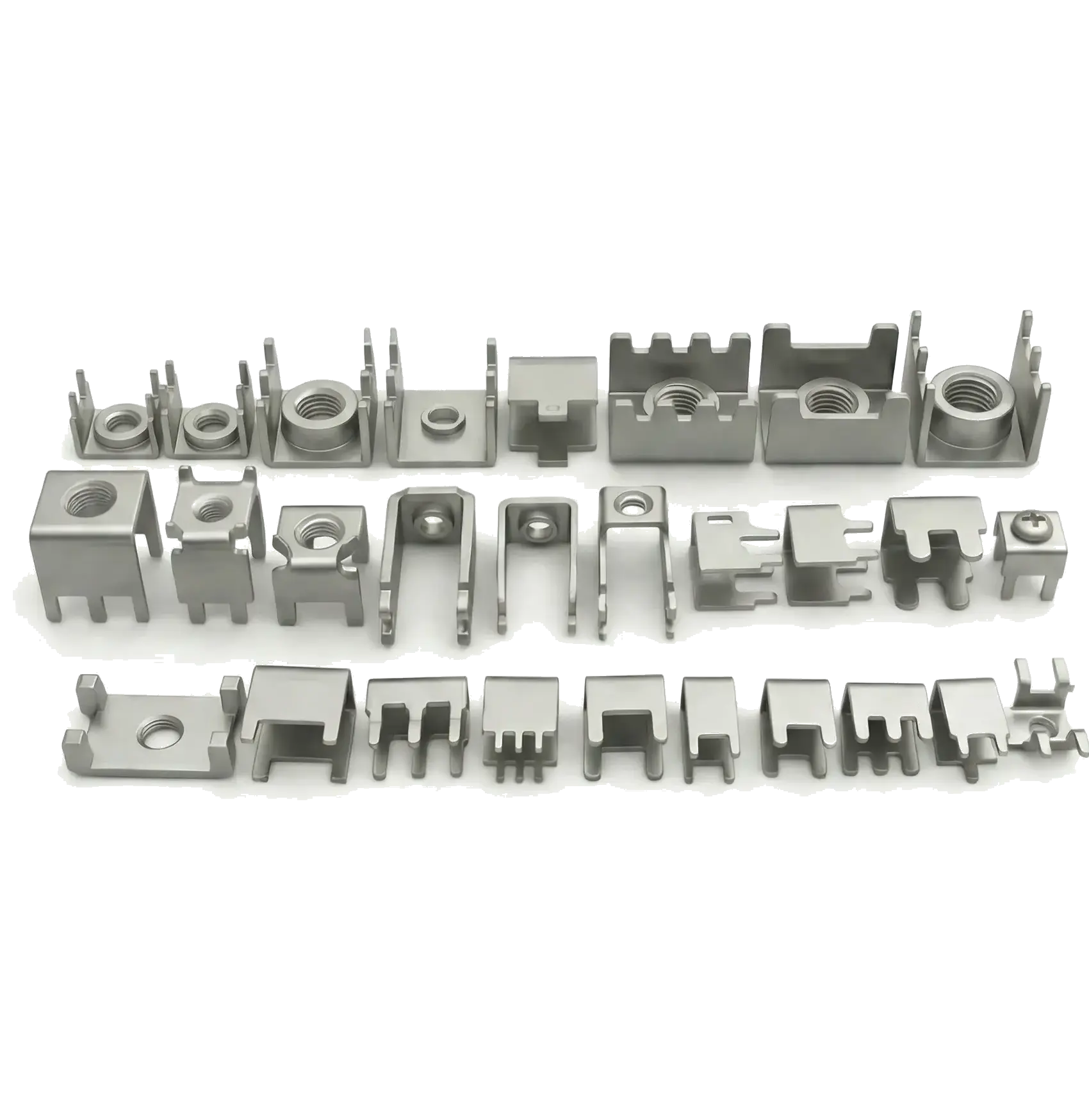
Why EV charging power modules often need welding terminals
Inside a power module, there are usually fixed board-mounted interfaces, external connection points, and positions that still need later fastening. In those cases, the value of a welding terminal is not only conductivity. It also standardizes interface position, soldering window, and assembly direction. When the interface role is clear enough, welding terminals help make board-level connections cleaner in production.
- Useful for bringing an external conductor onto a PCB or power board at a fixed interface point.
- Useful for volume projects that need a defined soldering window and mounting direction.
- Useful when the design also involves screw fastening, copper strap transitions, or module interfaces.
- Useful when the project wants less ad-hoc routing and manual adjustment on site.
Which positions deserve board-mounted welding terminals first
| Application point | Why a terminal fits better | Main design focus |
|---|---|---|
| Power-board input and output interface | The interface position is fixed and makes it easier to bring conductors onto the board in a stable way | Solder area, fastening direction, and keep-out space |
| Copper strap or flat conductor transition point | Helps define the relationship between external conductors and the board connection more clearly | Load path, pad window, and assembly order |
| Modular service or replacement position in the cabinet | Helps standardize the interface and reduce assembly variation | Service space, handling motion, and fixing strength |
When a busbar or wire harness should stay in place
If a section behaves more like a fixed main-current bus, a short board-level path, or a distribution node, a busbar is often the better fit. If the path is longer, needs detours, or includes service-related motion, a harness usually remains more practical. A welding terminal is strongest when it manages the interface role rather than replacing every other connection form.
| Approach | Best role | Main caution |
|---|---|---|
| Welding terminal | Board-mounted interfaces, copper strap transitions, and downstream fastening points | Confirm soldering window, mechanical load, and assembly direction early |
| SMD busbar | Fixed high-current short paths, distribution nodes, and compact conductive transitions | Layout, temperature rise, and insulation spacing need early review |
| Wire harness | Longer routes, flexible detours, and positions with more service movement | The route is flexible, but space use and repeatability still matter |
Five questions to answer before selecting
1. Does the terminal carry the main current path or mainly the interface transition
If the terminal mainly serves as an interface transition, structural definition, soldering area, and fastening stability usually matter more than simply increasing size. If it also carries the main current path, section size, heat spreading, and contact area must be evaluated together.
2. Is the soldering window suitable for production rhythm
If the pad area, solder flow direction, or nearby component height are poorly matched, volume production can quickly run into rework and position-shift issues. In power modules especially, pads, keep-out areas, and assembly fixtures should be reviewed as one package.
3. Will downstream fastening or cable pull feed stress back into the solder joint
Many problems come not from pure electrical capacity but from screw fastening, cable weight, or copper-strap pull transferring mechanical load back into the soldered area. When that risk exists, the load path should be separated and reviewed early.
4. How frequent is the service action
If modules are replaced, pulled out, or serviced often, the interface design must leave enough operating space. A terminal is good for defining a clear board-level interface, but that does not mean it should absorb every moving connection.
5. Does the project prioritize consistency or routing freedom
When the program is already production-oriented, welding terminals help standardize the interface definition. If paths and structural limits are still changing often, the adaptability of a harness may still be more useful for that stage.
A more practical decision sequence
- Separate the main-current paths, interface paths, and service paths inside the power module.
- Confirm which positions need fixed board mounting and which need flexible movement.
- Evaluate soldering window, downstream load path, and assembly order together.
- Then decide how terminals, busbars, and harnesses should split the work.
FAQ
Can a welding terminal replace a busbar inside an EV charging power module?
At some interface points, yes. But it is usually better not to make one part type carry every role. A more practical division is to let busbars handle fixed main-current routes, terminals handle board-level interfaces, and harnesses handle flexible paths.
Is a larger board-mounted terminal always safer?
No. Size is only an outcome, not the full logic. If the soldering window, load path, and mounting direction are not addressed together, simply increasing size may not improve stability.
What is easiest to miss in charging-module terminal design?
The long-term effect of downstream fastening and cable pull on the solder joint is often underestimated. Many solutions look acceptable electrically but expose structural weakness during assembly and maintenance.
Conclusion
Selecting a welding terminal for an EV charging power module is not about replacing every other connection method. It is about assigning board-mounted interfaces, fixed main-current routes, and flexible connections to the parts that fit them best. Once conductive path, soldering window, and load path are clarified early, the production plan usually stabilizes much faster.