


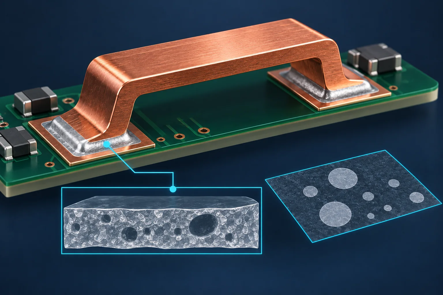
For an SMD busbar X-ray void report, agree the region of interest (ROI), segmentation and reported quantity first. If the agreed metric is a 2D projected-area fraction, calculate identified void area within the ROI divided by agreed ROI area, times 100%. This is not automatically the three-dimensional void volume fraction.
Make the percentage reproducible
Nordson's X-ray application overview lists void percentage, area and solder-layer separation as distinct inspection outputs. Specify which output is required. This article proposes reporting practices, not a universal void limit for all SMD copper busbars.
A denominator example
Hypothetically, 20 mm² of identified projected void area divided by a 200 mm² ROI gives 10%. Using 250 mm² as the denominator gives 8%, without changing the joint. Define whether the ROI follows a nominal land, actual solder projection or another agreed region before comparing suppliers.
| Record | Include | Purpose |
|---|---|---|
| Original image | Sample identity, view and acquisition settings | Avoid judging only cropped images |
| ROI | Overlay, area in mm² and definition | Fix the denominator |
| Segmentation | Threshold, filtering and manual changes | Explain included pixels |
| Result | Total area, largest projection and location | Retain local concentration information |
| Measurement conditions | Pixel size, calibration and software version | Support repeatable review |
Do not double-count overlapping projections
For a defined 2D metric, use the union of segmented projected regions in the selected image. Overlapping projected locations must not be added twice. Keep different views and separated layers as identified results; summing their areas indiscriminately changes the metric.
Agree segmentation using the same original images and retain overlays. Lowering a reported percentage through threshold adjustment is not process improvement. Evaluate whether noisy, saturated or heavily obscured images are suitable for the task.
Depth and volume need a different assessment
ZEISS's technical note on laminography and 3D X-ray microscopy discusses reconstruction, missing angular information and artifacts. If depth, layer assignment or volume fraction matters, agree the appropriate reconstruction, resolving capability and segmentation basis with the inspection provider. A “2.5D” label or voxel size alone is not proof of accurate volume measurement.
Write the inspection boundary into procurement documents
Provide solder geometry, copper thickness and PCB construction in an SMD busbar enquiry. Define whether the concern is overall fraction, local clustering or a critical current path. Agree limits from contractual requirements and assembly validation rather than borrowing BGA limits. See busbar void and wetting troubleshooting for process investigation.
FAQ
Does a low projected void percentage guarantee acceptable temperature rise? No. Validate the actual electrical and thermal assembly.
Are two 10% reports directly comparable? Only after checking compatible ROI definitions, imaging and algorithms.
AI-generated void-analysis concept, not a real radiograph or Hongchuan test result. Areas are hypothetical calculations; no universal acceptance percentage is asserted.