


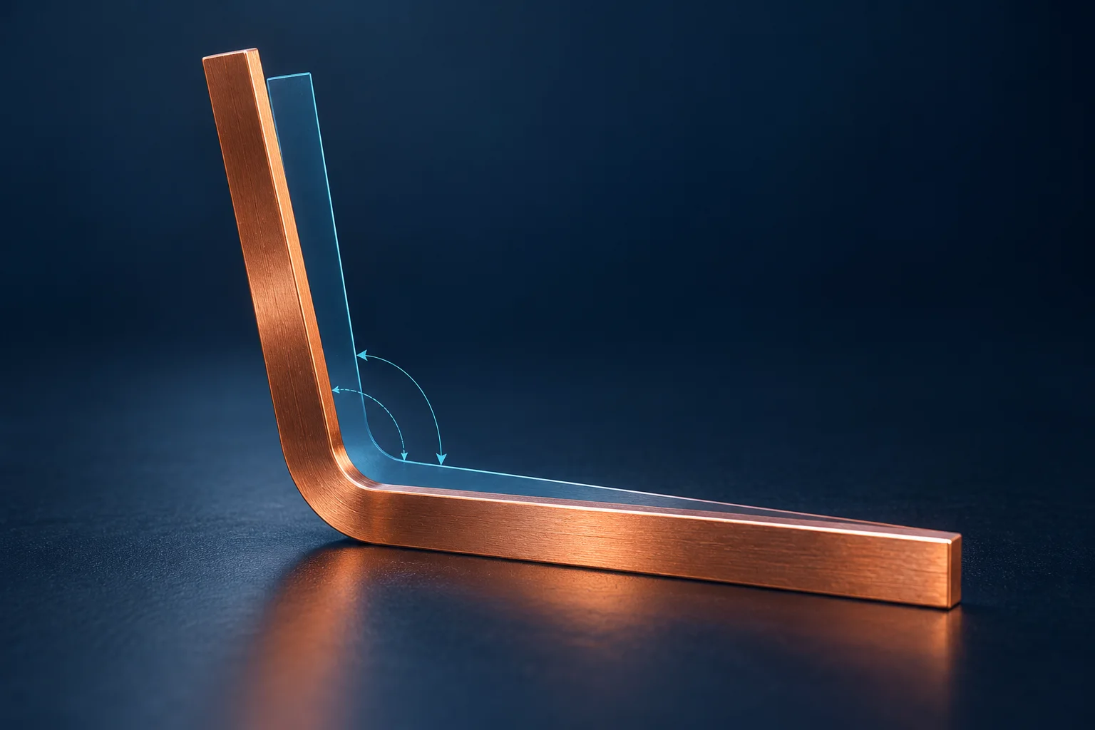
Inspect a bent PCB busbar in the condition specified by its drawing. Tooling geometry, the loaded forming angle and the released part angle can differ. If the requirement applies to the free state, a reading taken while the part is forced against tooling is not the free-state result.
Define the angle and load state
COMSOL's sheet-metal forming example separates forming and released angles and explains elastic recovery. Its example uses aluminum alloy; neither its angles nor material parameters are copper-busbar data.
Assume an agreed included-angle definition between two straight legs. A loaded angle of 90.0° followed by a released angle of 92.0° gives a +2.0° change under that definition. A rotation-from-flat convention changes the expression and sign. Attach the measuring definition rather than reporting an unexplained “springback angle.”
| Record | Specify | Do not substitute |
|---|---|---|
| Tool geometry | Tool version and nominal shape | Part angle |
| Loaded angle | Load state and angle definition | Machine stroke display |
| Released angle | Free or constrained state and timing | A fixture-forced result |
| Measuring location | Straight faces, fitting regions and section | A fit that includes the bend radius |
Document support conditions
Use the approved locating method and record contacted datums and clamping. If the drawing specifies a constrained condition, use and document it. Do not force a part into the desired shape and describe the result as free-state acceptance.
Choose a suitable angle-measuring method and preserve location photographs and readings. Loaded-state investigations belong to qualified equipment and process personnel using approved safety procedures, not hand-held checks inside moving tooling.
Validate compensation for the actual process
AutoForm describes modifying tooling geometry using calculated or measured springback. A single assumed +2.0° result does not authorize a universal 2.0° tool correction. Match material condition, thickness, radius and forming conditions before validating a change.
For bent PCB copper busbars, provide the finished drawing, angle convention, tolerance and inspection state. K-factor and flat-length calculations address the unfolding model; released-angle behavior requires separate verification.
Questions
Does changing K-factor eliminate springback? Evaluate the unfolding model and forming angle separately.
Does correct fit in a bracket prove the free angle? Inspect each specified condition and keep the results identifiable.
References
COMSOL forming and release example; AutoForm springback compensation.
The cover is an AI springback concept, not a Hongchuan forming or inspection record. Example angles establish no tool setting or forming capability.