


Do not accept SMT nut bottom-surface coplanarity solely because a part does not rock on a plate. Define the solder-contact surfaces, free or restrained state, sampling, plane evaluation and tolerance. Report continuous-surface flatness, multiple-contact coplanarity and assembly tilt separately.
Define the drawing requirement first
ISO 1101:2017's public description covers geometrical-tolerance expression for form, orientation, location and run-out. Its catalogue page is not the full standard. A drawing stating “coplanarity 0.05 mm” without surface boundaries or evaluation rules needs clarification before supplier and purchaser choose different inspection methods.
| Check | Feature | Does not establish |
|---|---|---|
| Bottom flatness | One specified continuous contact surface | Thread-axis orientation |
| Multiple-contact coplanarity | All designated contact regions | Acceptance based on one region |
| Assembly tilt | Part relative to agreed PCB or fixture reference | Free-state surface flatness |
| Thread specification | Thread size and inspection requirement | Outer diameter or bottom geometry |
Do not flatten the defect with the fixture
Attach fixture photographs showing support locations, orientation and contact force. Keep free-state and tightened-state measurements separate. Check whether a contact probe can deform the feature. For optical measurement, document reflections, obstruction and rejected-point rules. Undisclosed clamping on the measured surface undermines comparison.
KEYENCE's flatness measurement overview discusses measurement methods and positioning effects. Distribute points across the relevant contact surface, including edges and interior, while excluding drawing-defined chamfers and non-contact regions. Sparse plane fitting can miss local distortion; agree point density for the actual geometry.
A height range is not automatically minimum-zone flatness
Suppose four hypothetical heights relative to an established inspection plane are 0, 0.03, −0.01 and 0.04 mm. Their range is 0.05 mm. It describes those points against that plane only. Changing the algorithm, sampling or fixture can alter the result. Do not label this automatically as minimum-zone flatness or declare acceptance without the agreed specification.
Retain raw coordinates, algorithm identification, point map, fixture state, calibration status and measurement uncertainty. Use the agreed decision rule near tolerance boundaries rather than selecting the smallest result from repeated placements. Apply the same controlled inspection document to first-article and incoming checks.
Connect incoming and soldered-part records
For an SMD nut, correlate bottom geometry with post-reflow height, tilt and wetting. Floating alone does not establish defective incoming flatness; review paste and thermal balance through the SMT nut reflow troubleshooting guide.
FAQ
Is a no-rocking check enough? It is a screen, not a numerical survey of all contact regions.
Is 0.05 mm a universal SMT nut limit? No. Geometry, soldering process, measurement capability and confirmed drawings determine requirements.
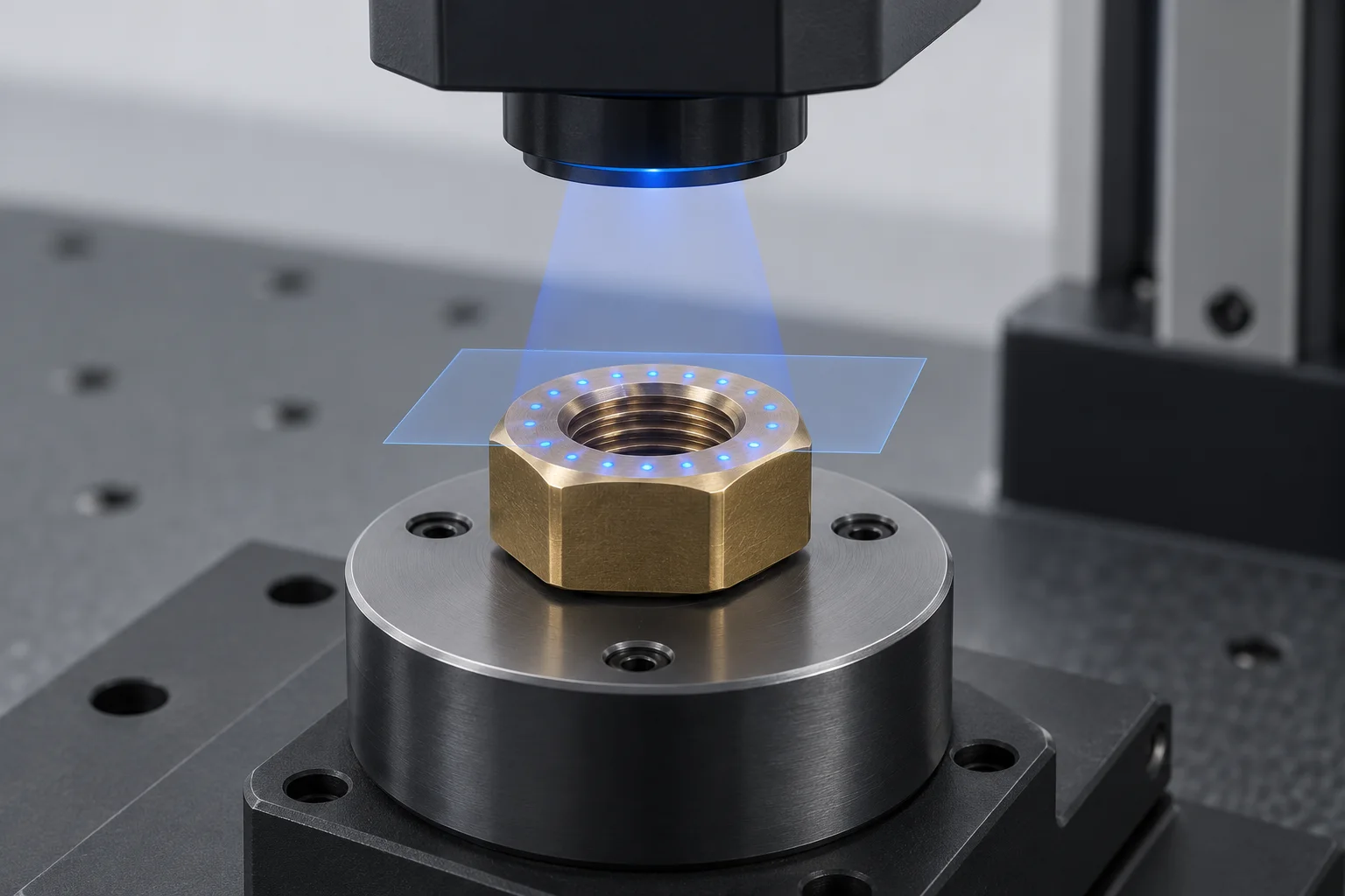
AI-generated metrology illustration, not Hongchuan inspection equipment or actual results. No universal coplanarity limit is asserted; hypothetical data explain reporting boundaries only.