


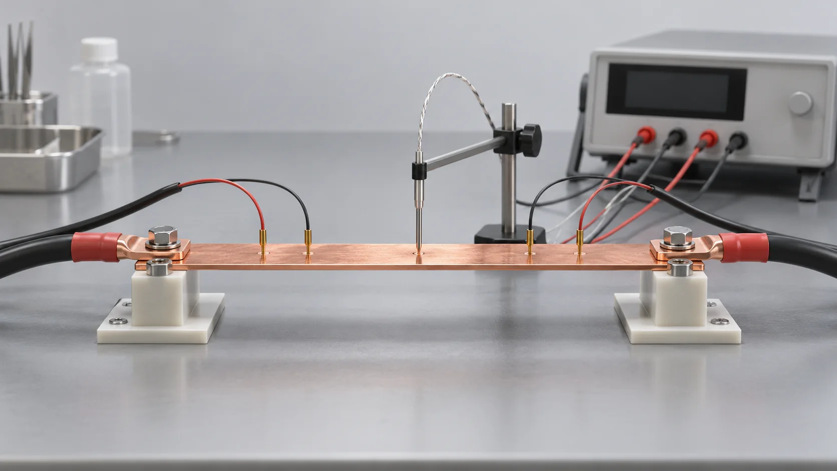
Direct answer For a known copper conductor at approximately uniform temperature, use R₂₀ = Rₜ/[1 + α₂₀(T − 20)] within the applicable temperature range. T is conductor temperature in °C and α₂₀ is the material's resistance temperature coefficient referenced to 20°C. Retain the measured resistance and temperature alongside the corrected result.
Define what can be corrected
The method is useful for comparing copper bodies with identical sensing boundaries. Approximately 0.0039 K⁻¹ is a preliminary value for high-conductivity copper. Precision acceptance requires material-specific or validated data and an agreed range. Original research preserved by NIST relates the coefficient to specimen conductivity; it is not a universal constant for every copper alloy.
A reading across a copper strip, brass terminal, solder and bolted interface includes different contributions. Contact behaviour can also change with temperature. Correcting the entire reading as pure copper can hide a connection problem. Separate the sections or compare the complete assembly at an agreed controlled temperature.
A hypothetical 100 μΩ example
Assume a copper section measures 100 μΩ at 60°C and use α₂₀ = 0.0039 K⁻¹. The temperature difference is 40 K and the denominator is 1.156, giving R₂₀ approximately 86.5 μΩ. Celsius and kelvin temperature differences have equal numerical values. Do not insert 333.15 into the expression T − 20.
| Report field | Example or requirement |
|---|---|
| Raw resistance and temperature | 100 μΩ at 60°C |
| Material and coefficient | Assumed high-conductivity copper, 0.0039 K⁻¹ |
| Reference and corrected result | 20°C, approximately 86.5 μΩ |
| Measurement conditions | Sense-point photo, current, duration and stability criterion |
Estimate the temperature contribution to uncertainty
For the same assumptions, a 1°C temperature error contributes approximately 0.0039/1.156, or 0.34%, to the corrected resistance locally. This does not include meter uncertainty, sensing repeatability or uncertainty in the coefficient. If the strip has a pronounced hot spot, improve temperature measurement and stabilisation before treating a single reading as the temperature of the whole section.
See the related guide to four-wire measurement and sensing boundaries. When comparing PCB copper busbar samples, agree the raw temperature, reference temperature and allowable measurement uncertainty.
Frequently asked question
Can tin-plated copper and brass jumpers share one coefficient?
Verify the substrate rather than judging its appearance. Coating contribution, geometry and sensing path determine whether a copper-body approximation is suitable. Brass needs its own material data.
Sources
- Copper for Busbars, Section 1.2.2.1.1.
- NIST archive, The Temperature Coefficient of Resistance of Copper.
Sources checked on 8 October 2026. Calculations are hypothetical examples, not Hongchuan product test data. The cover is an AI-generated engineering illustration, not a product photograph or test record.